Variation of the Rigid Constraint Vector Between Stereo Cameras Over Time.
Acquisition using lightweight platforms and data processing for underwater photogrammetry
Ph.D. Defense
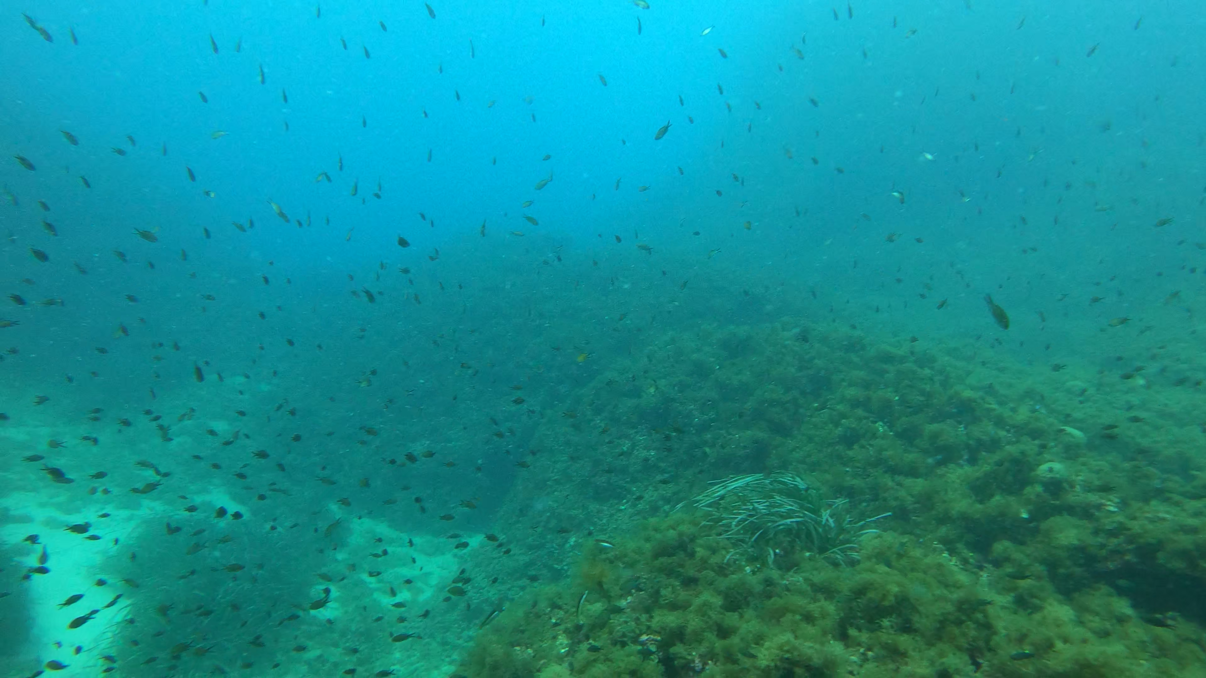
Underwater Environment
Context
Objectives:
- Conduct on-site data collection
- Utilize affordable platforms and sensors
- Achieve accurate pose estimation
Environment:
- 0 to 40 meters depth
- Nearshore areas
- Natural lighting conditions
Sensors


| Price | Control | |
|---|---|---|
| Industrial | High | Excellent |
| Consumer | Low | Basic |
- Aim for affordable equipment.
- Ensure modularity and control.
Vectors
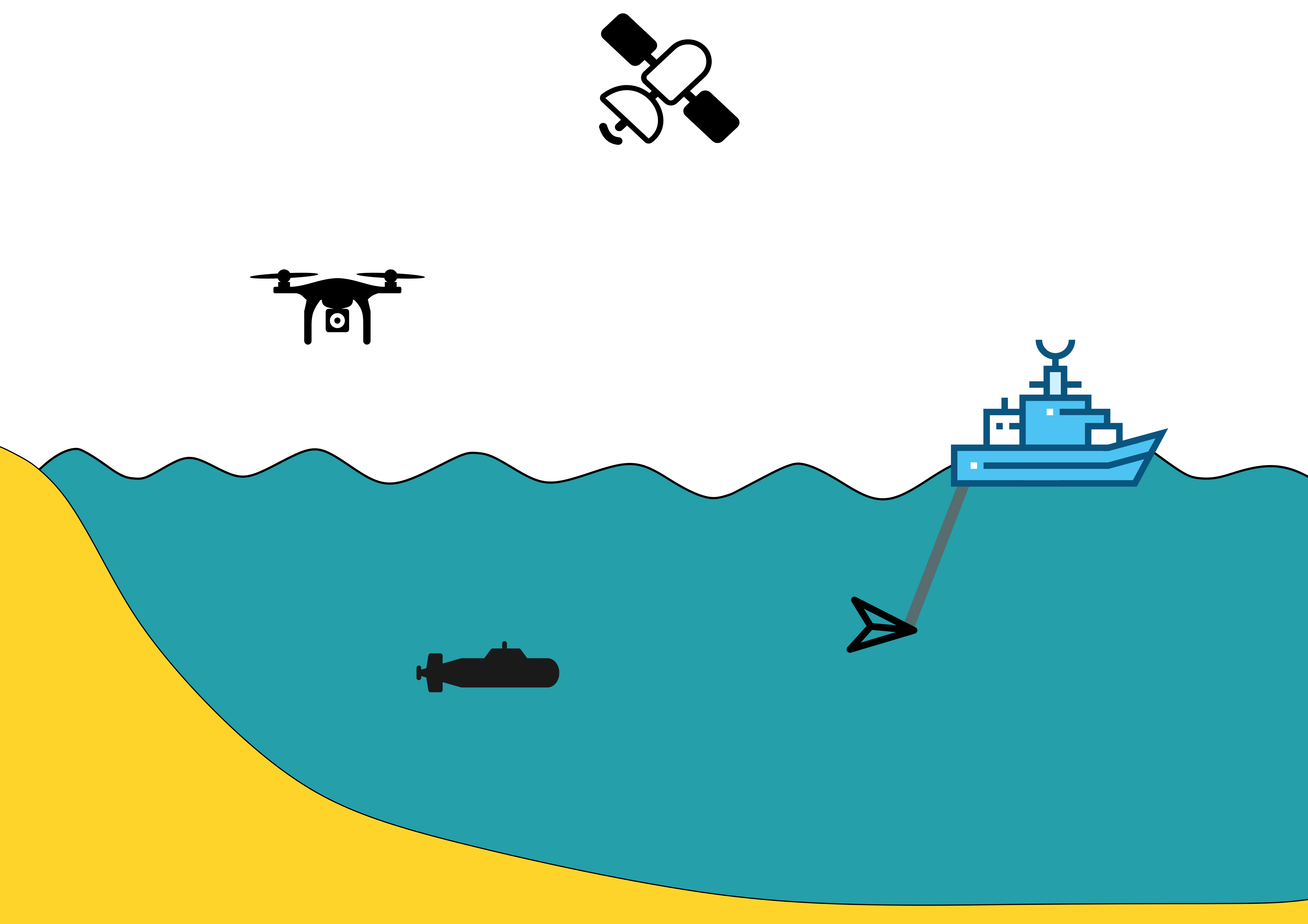
- The seabed can be mapped using different platforms:
- Unmanned Aerial Vehicles (UAVs).
- Unmanned Surface Vehicles (USVs).
- Towed Underwater Vehicles (TUVs).
- Autonomous Underwater Vehicles (AUVs).
- These platforms share a common robotic architecture adaptable to various vehicle types.
Systems Used for Underwater Photogrammetry
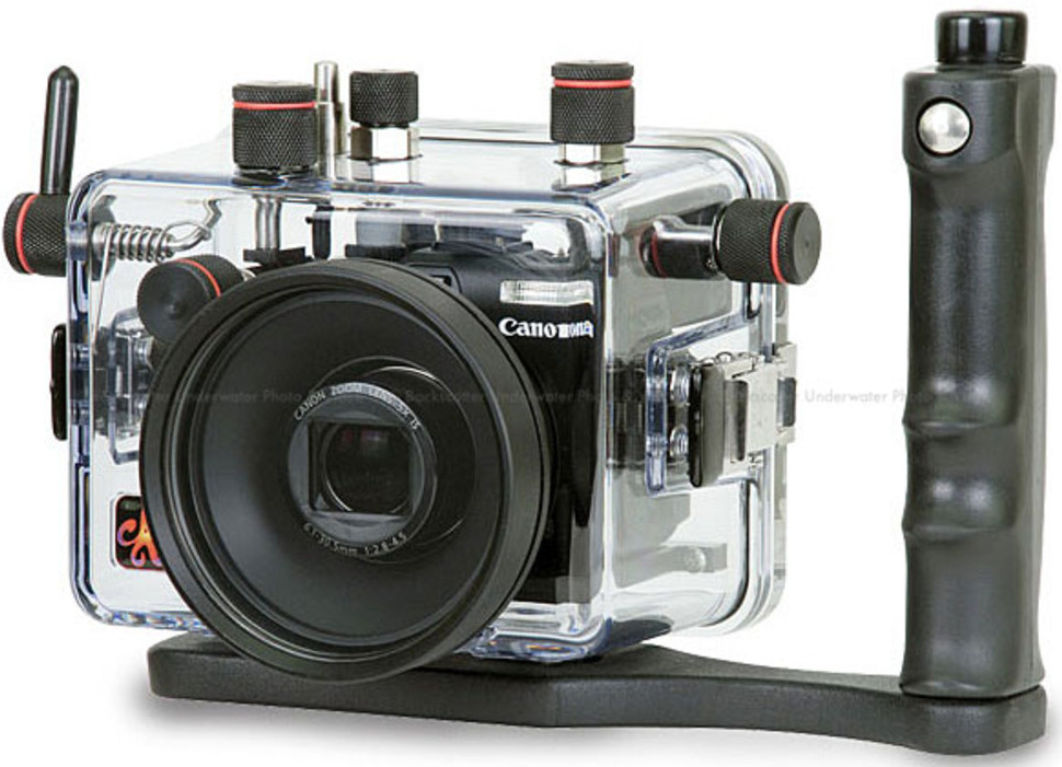
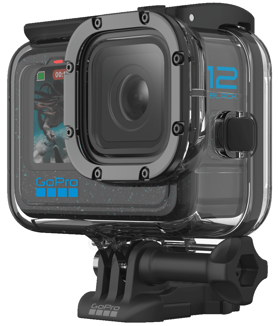
Equipment:
- Primarily GoPro cameras.
- Off-the-shelf Remotely Operated Vehicles (ROVs).
Drawbacks:
- Lack of synchronization between cameras.
- Limited control over image acquisition parameters.
- No integration with the vector platform.
![]()
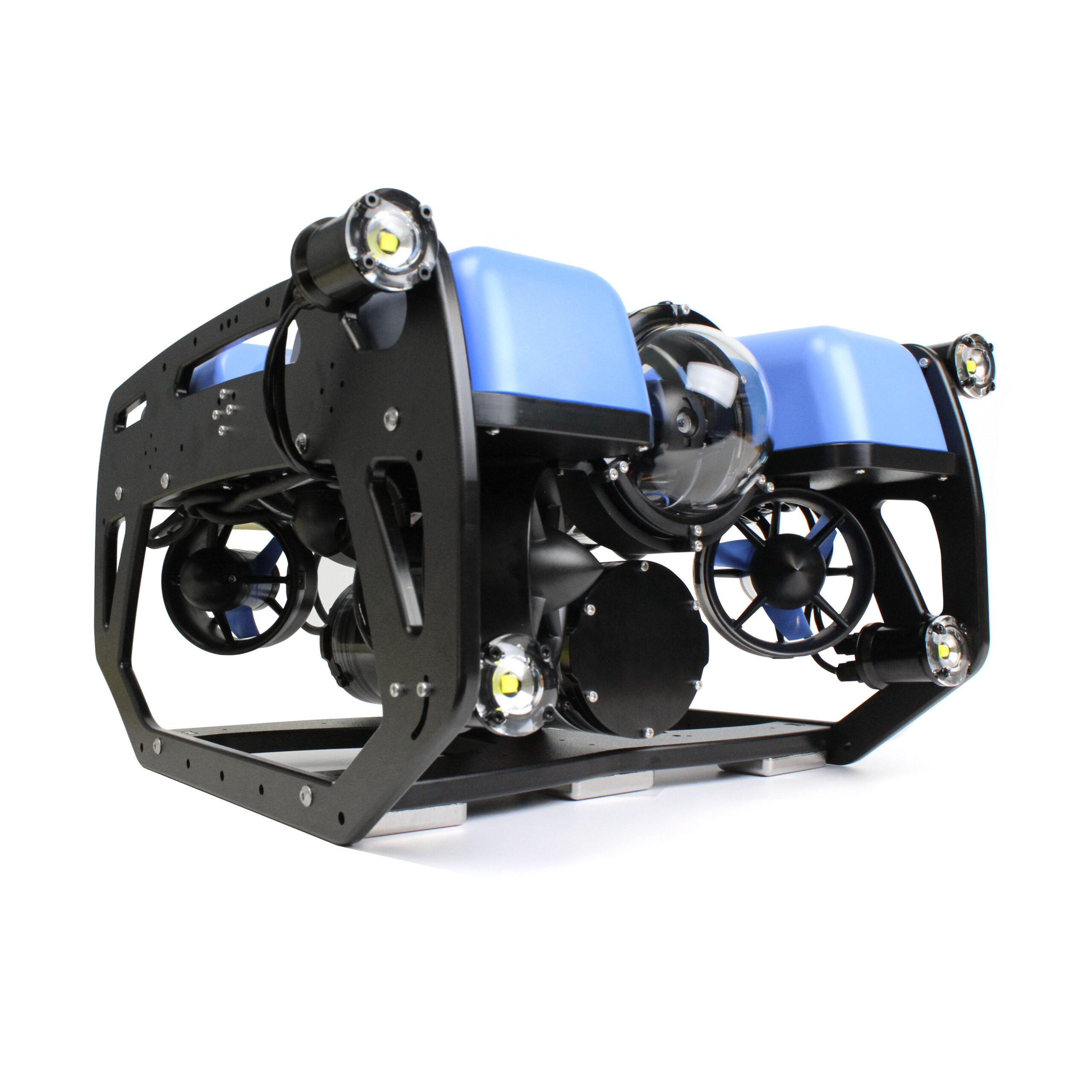
Our multi-camera synchronized underwater system

Contributions:
- Hardware and software architecture development.
- Low bandwidth communication protocol for the camera.
Features:
- Each camera can operate:
- Independently.
- In a synchronized array.
- Connected to a robotic platform.
- Modular design:
- Interchangeable lenses.
- Additional modules such as screens can be attached.
- Supports connection of multiple cameras.
![]()
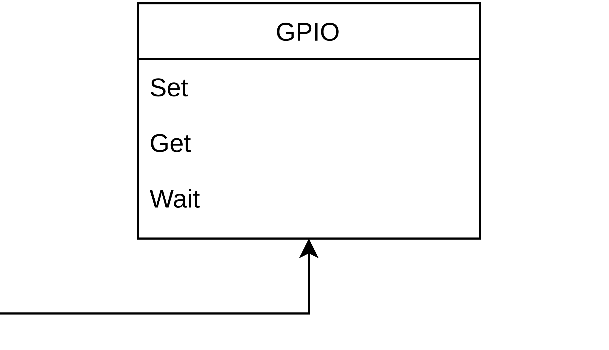
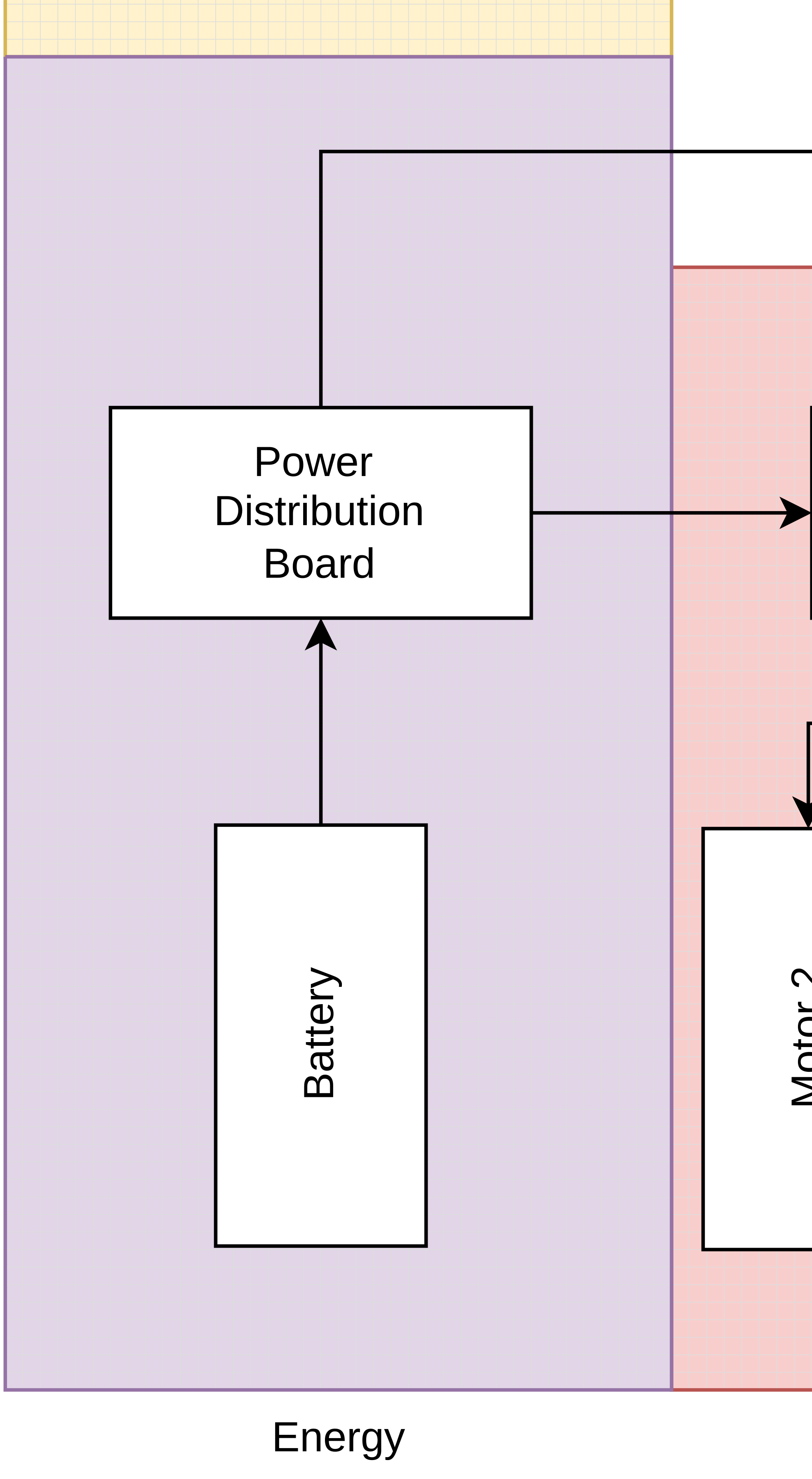
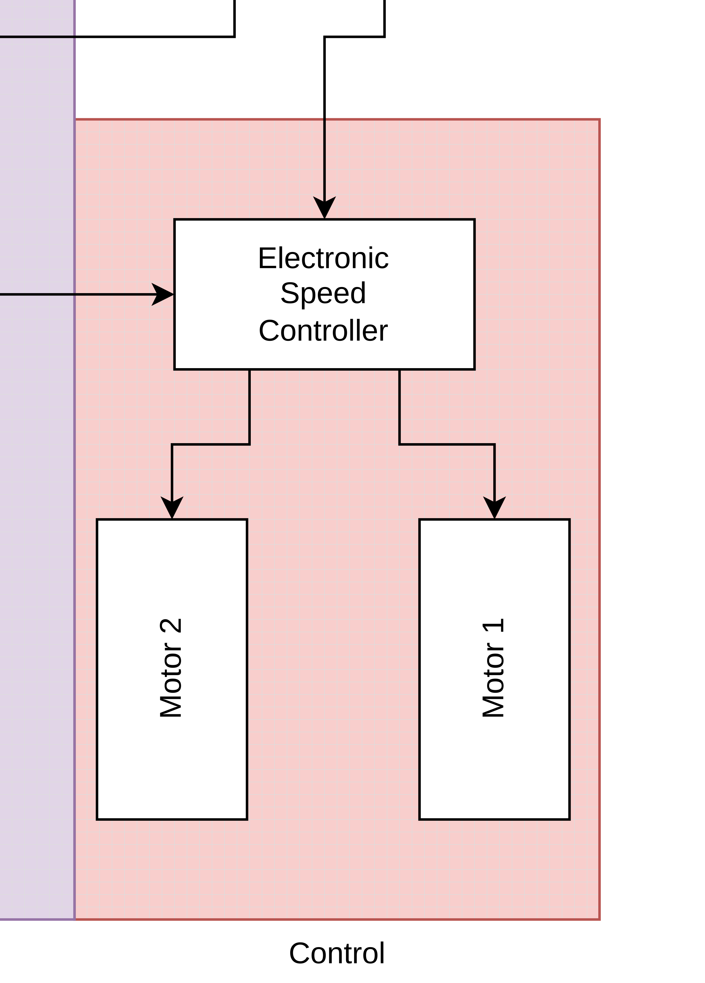
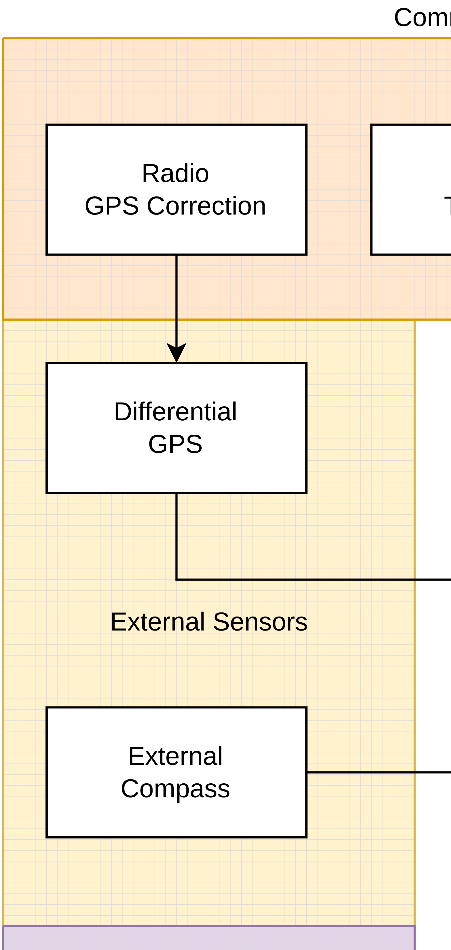
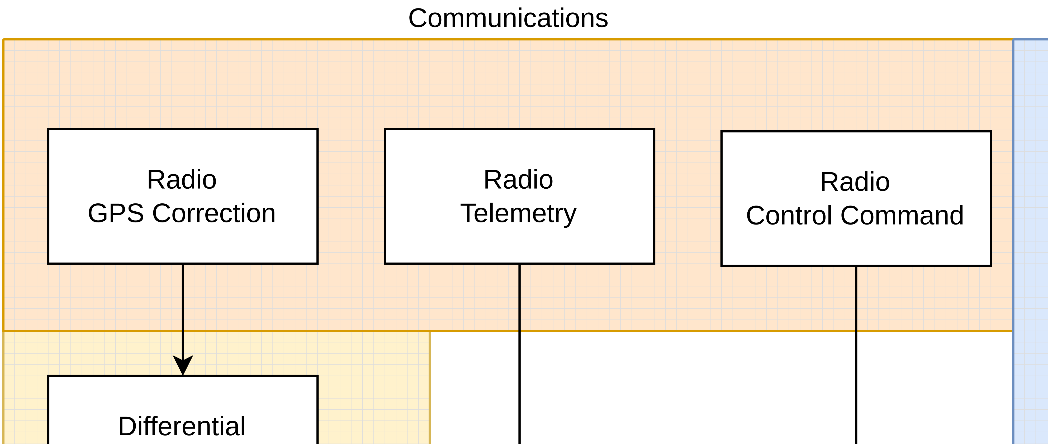
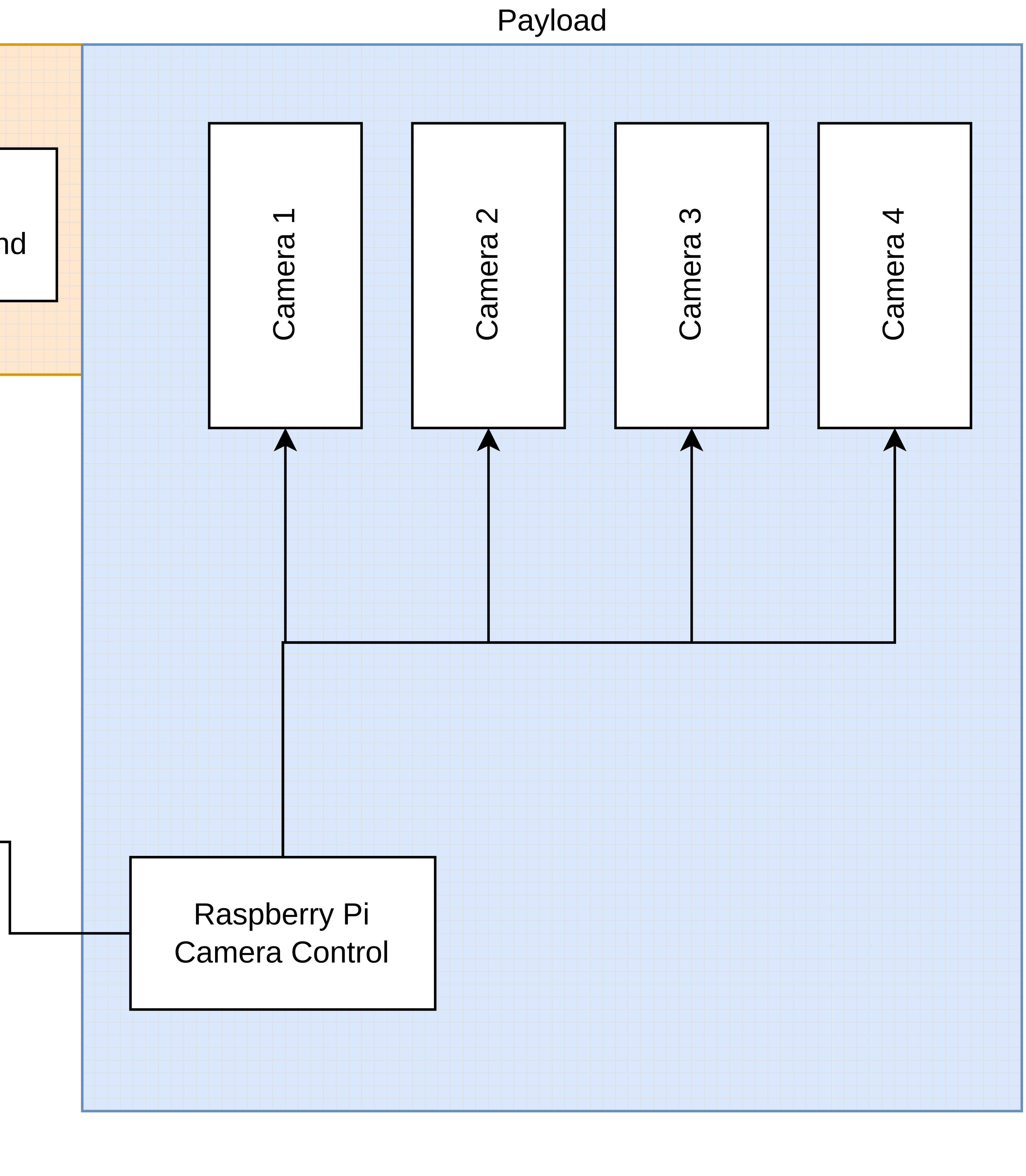
Sensor architecture - Hardware


![]()
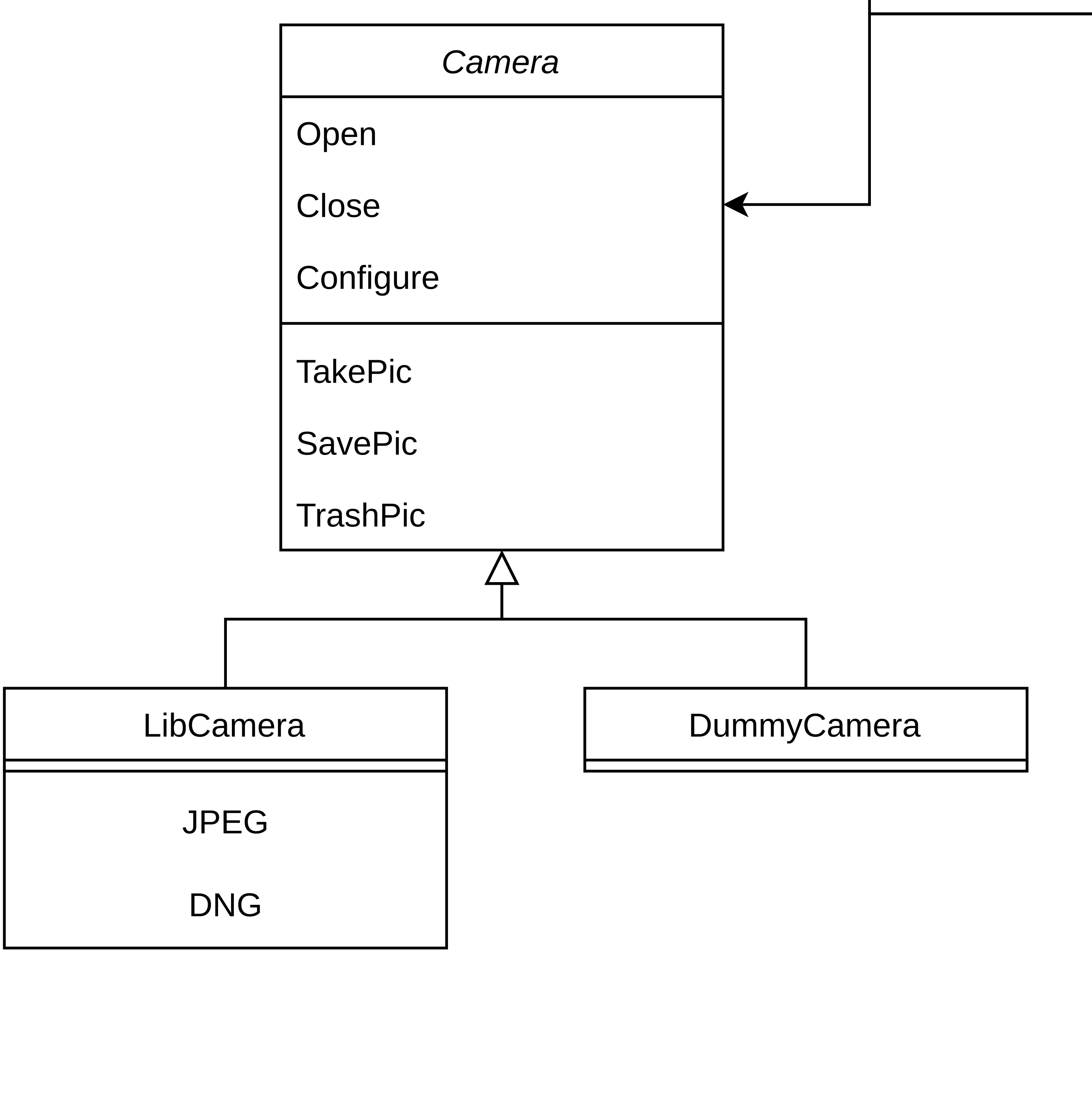
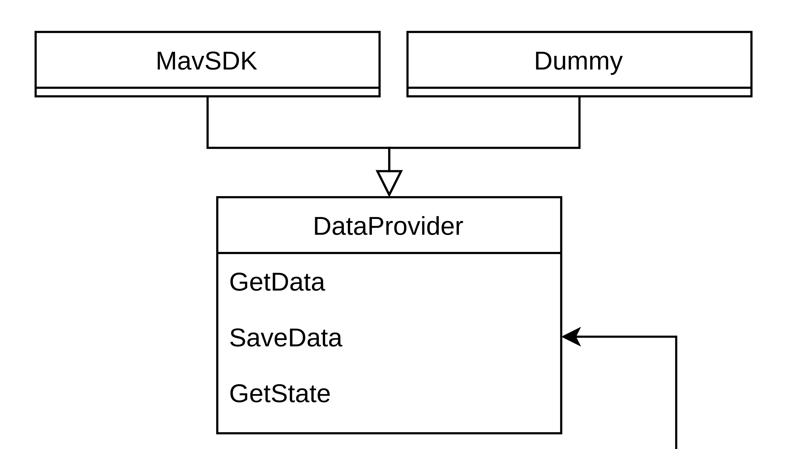
Sensor architecture - Software


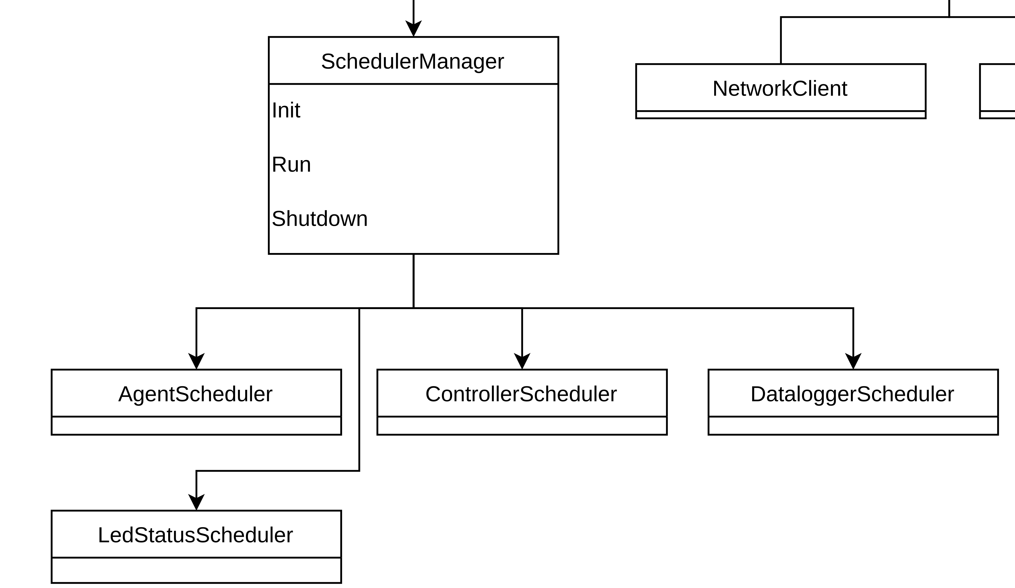
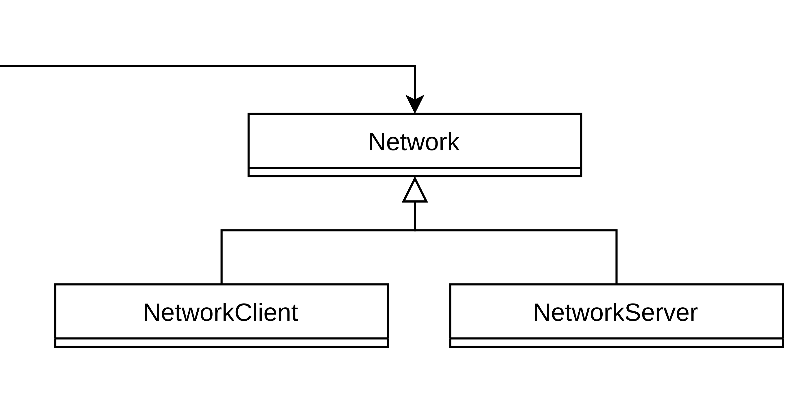
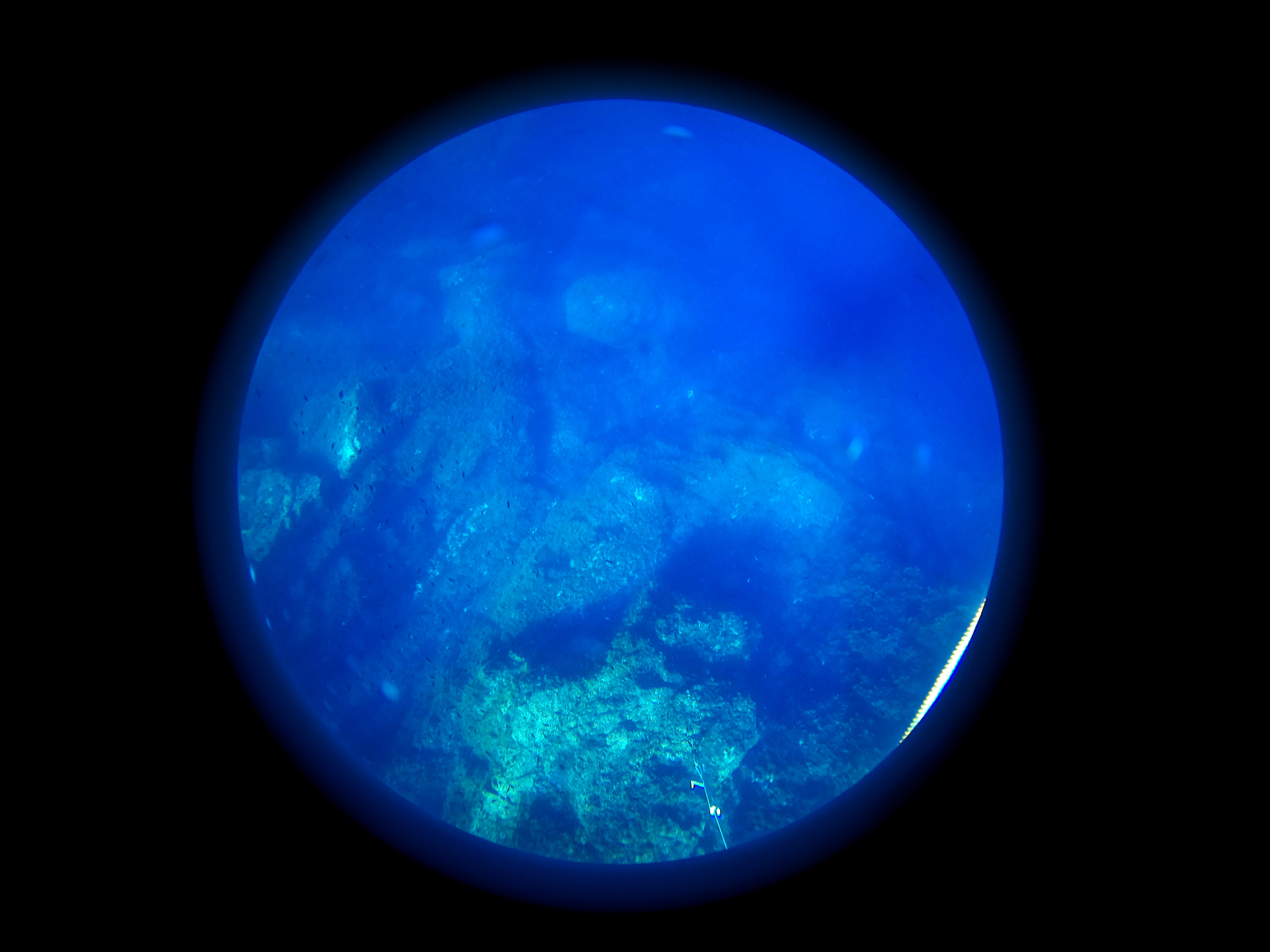
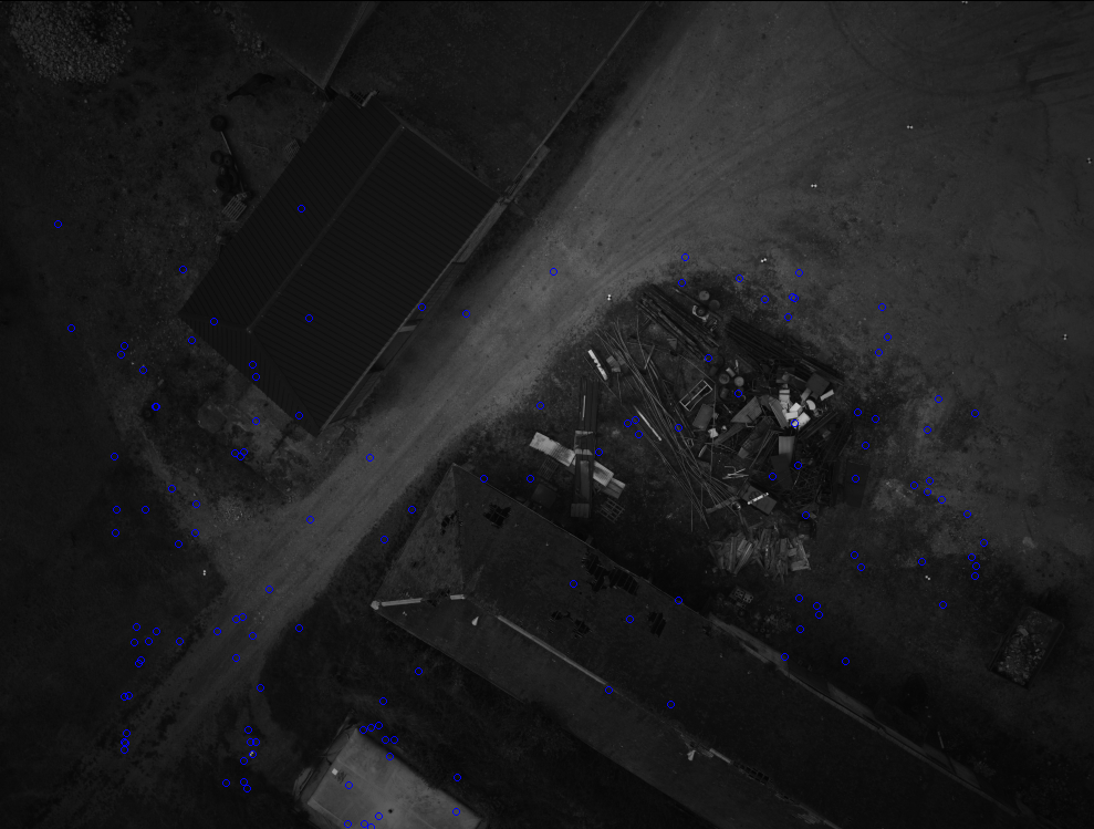
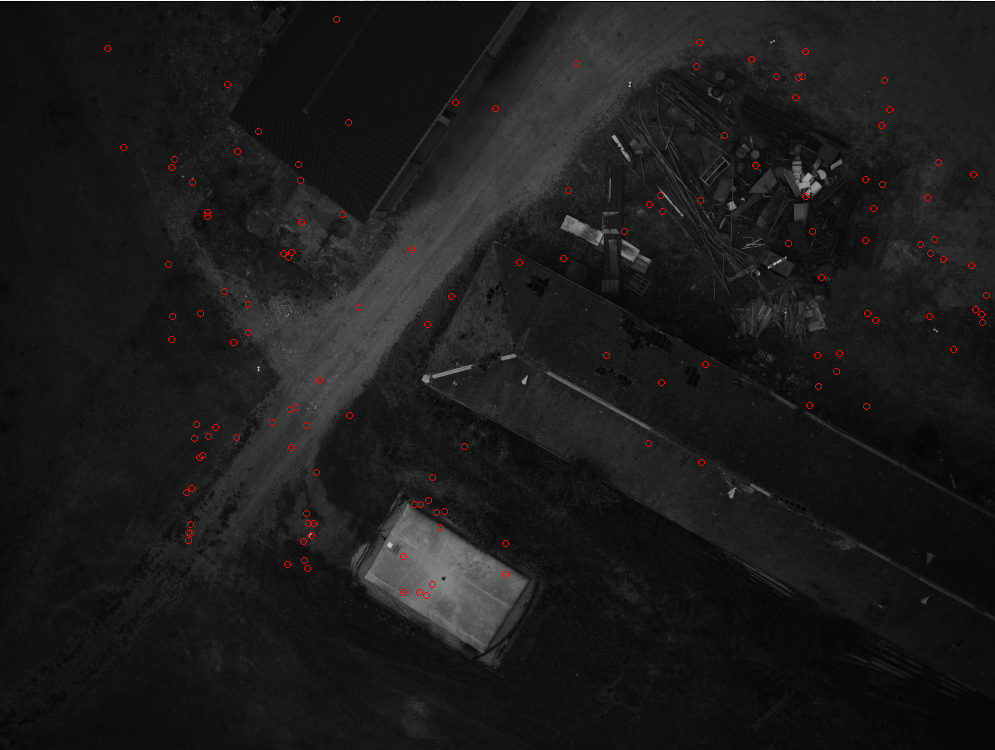
![]()
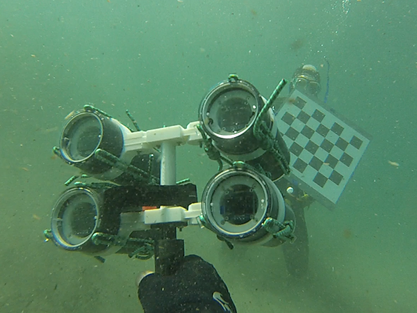
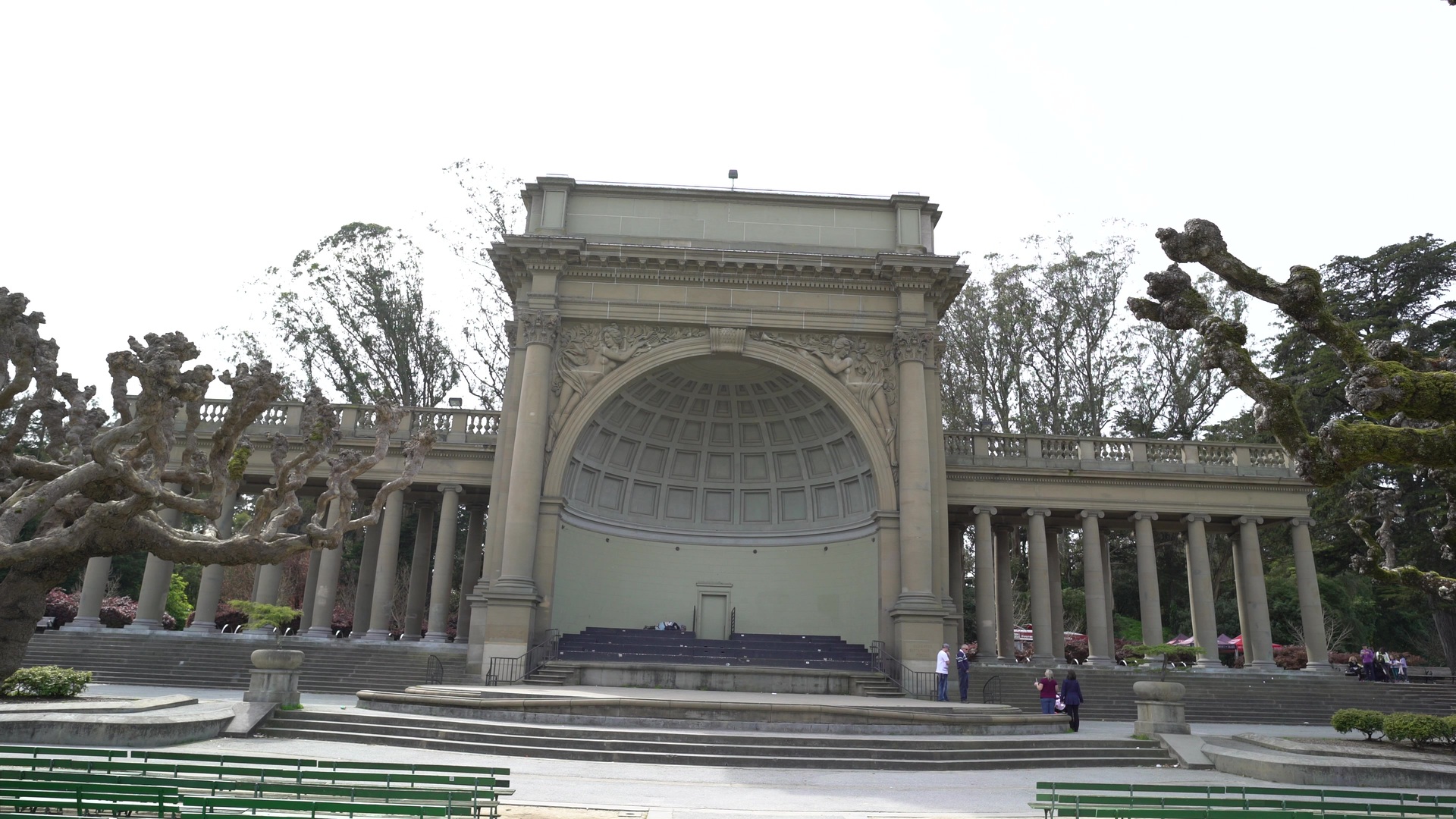
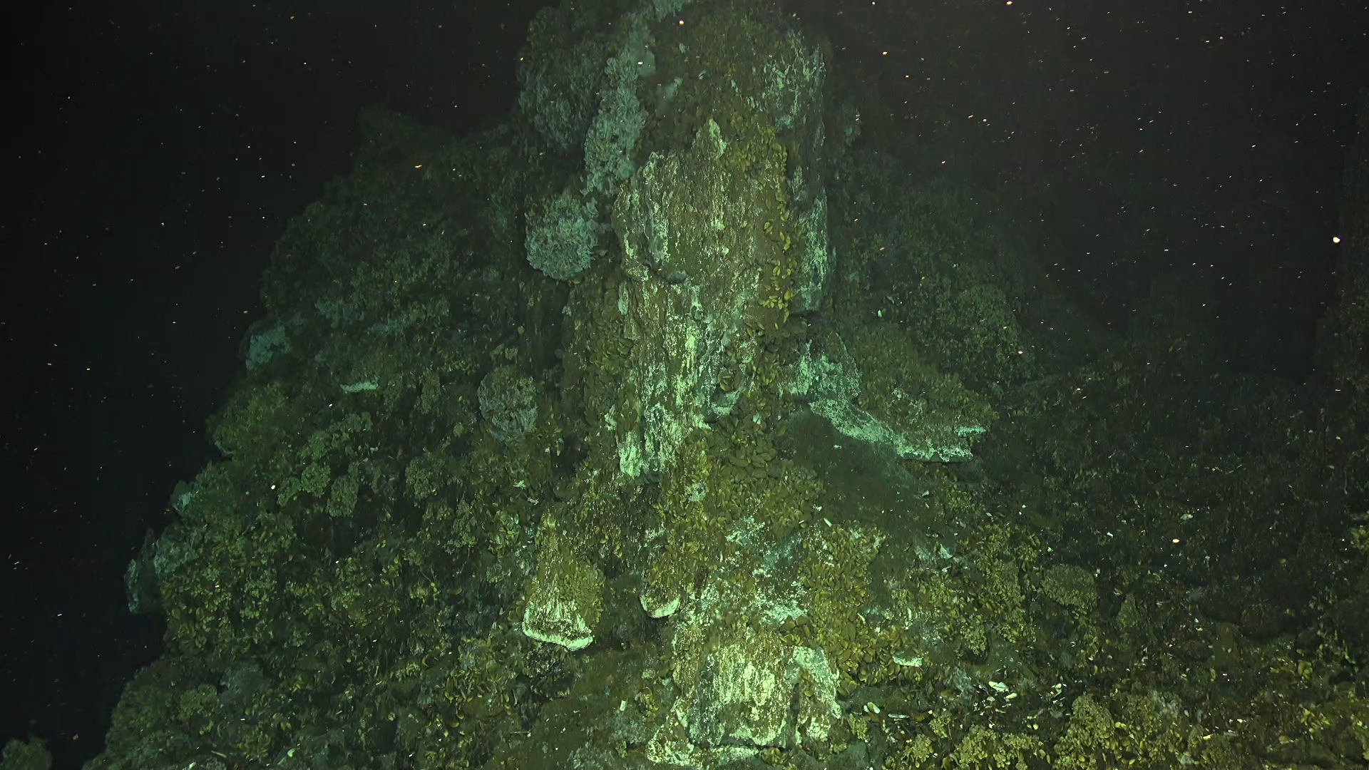
Acquired images examples
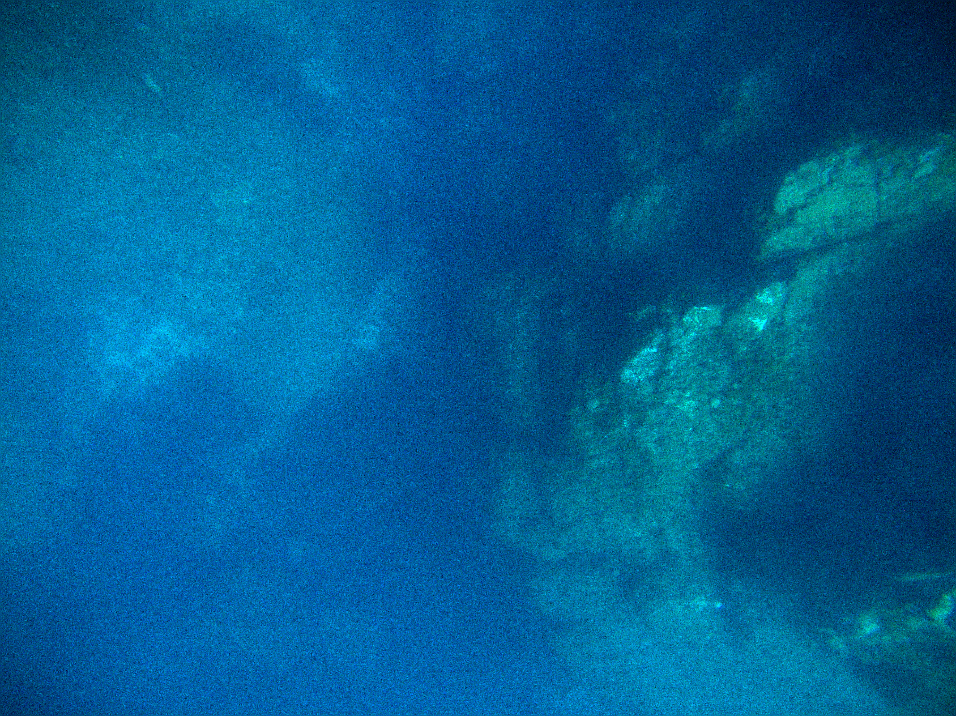
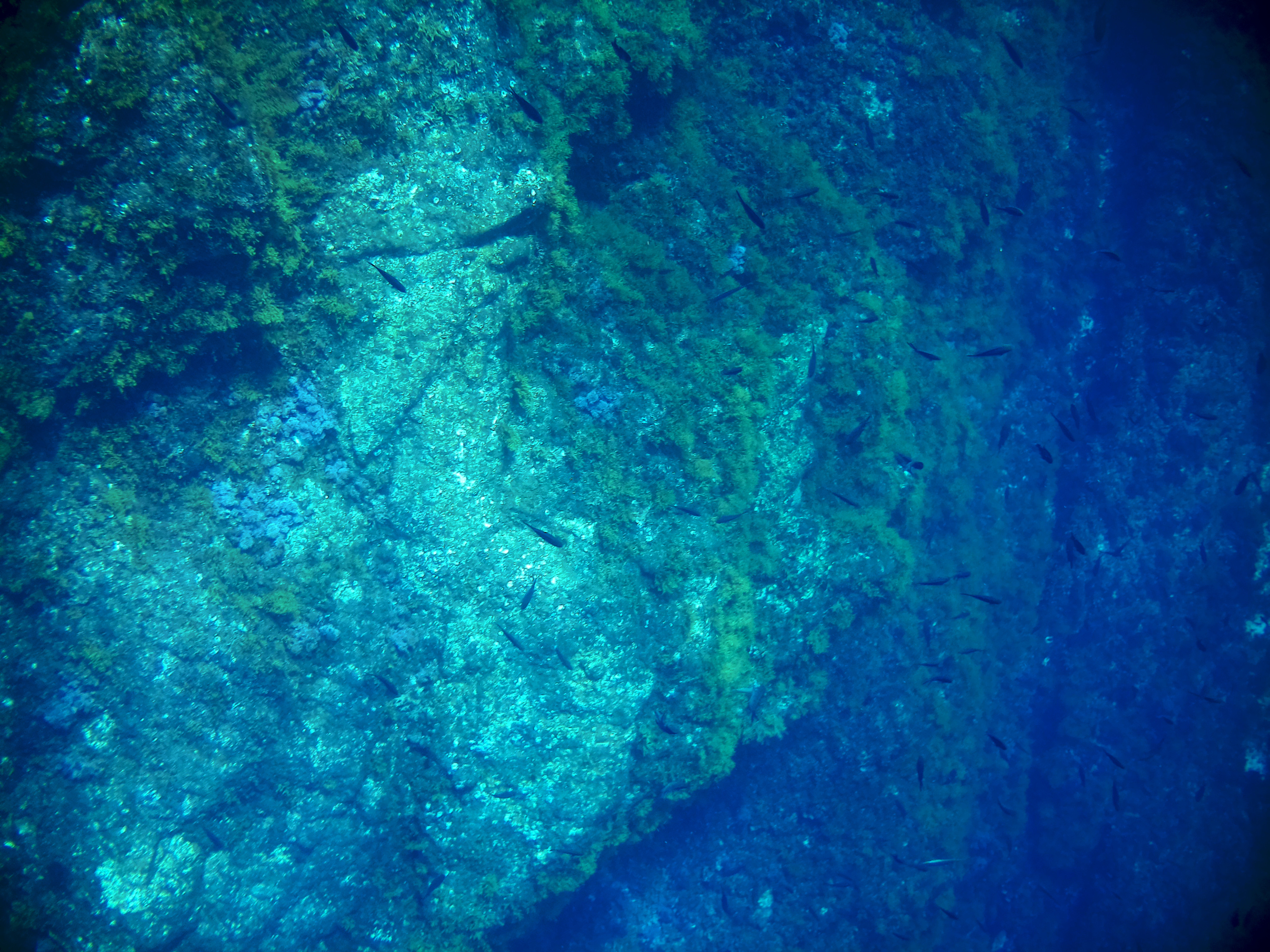
Characteristics:
- Rigid base linking the cameras.
- Minimizes pose estimation uncertainties.
- Synchronized for capturing dynamic scenes.
- Expands field of view.
Metrics:
- 1 ms synchronization between cameras.
- 1 image per second.
![]()
Modular Autonomous Unmanned Surface Vehicle
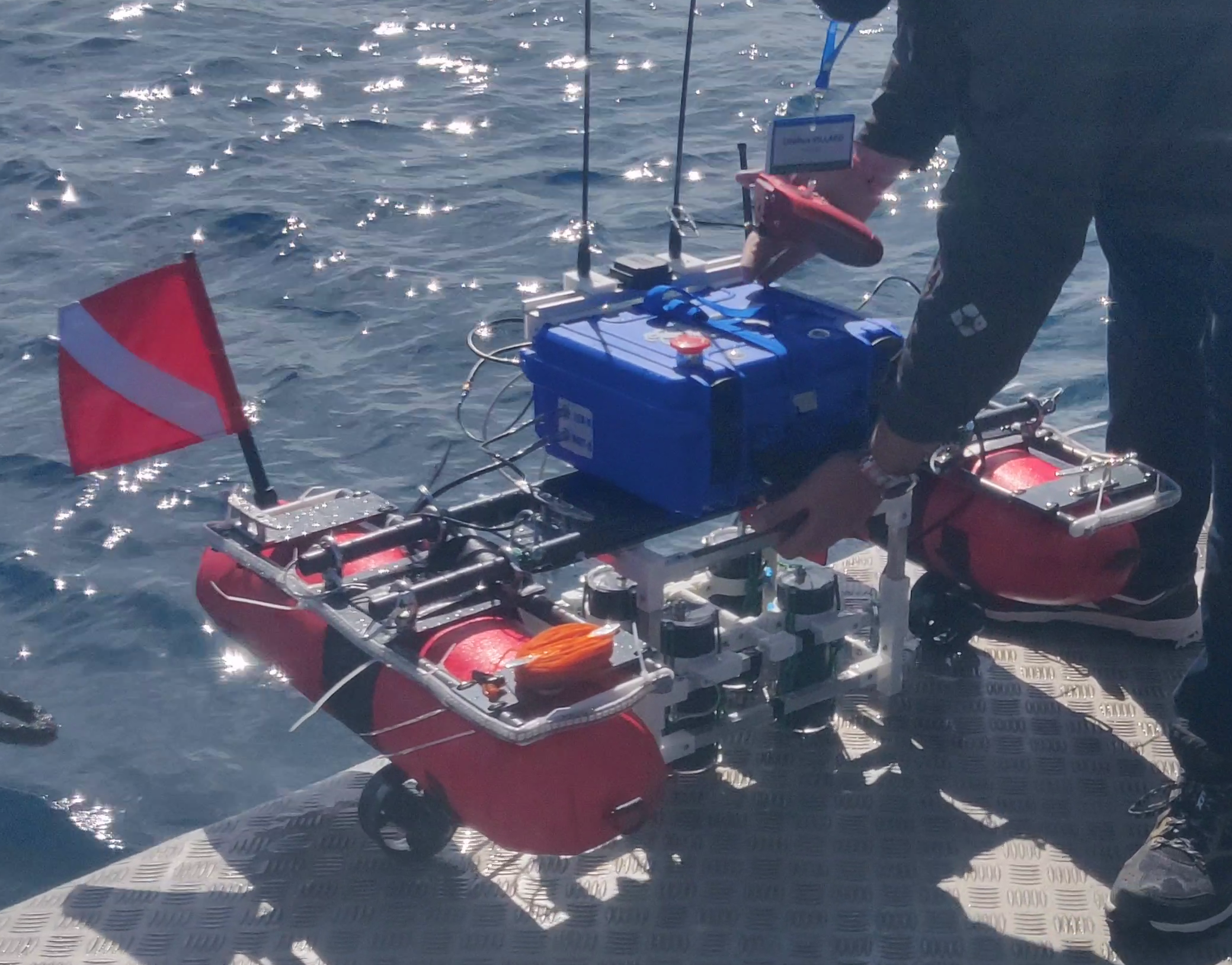
Contributions:
- Hardware electronics architecture.
- Software port of Ardupilot on ESP32.
- Modular platform architecture:
- Operable by one person.
- Dismountable for train transport.
Features:
- Manual long-distance control.
- Autonomous trajectory planning.
- Remote camera triggering.
- Global position estimation for image acquisition.
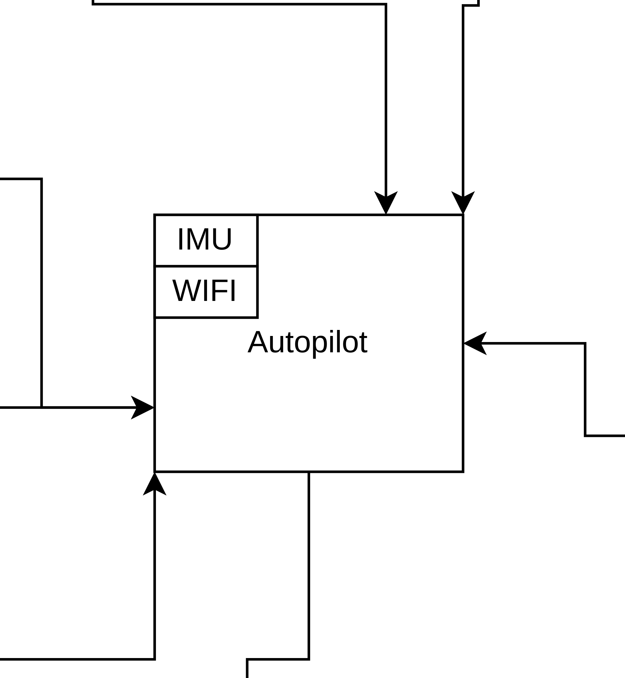
![]()
Vector architecture - Hardware


![]()
Vector autonomous capabilities

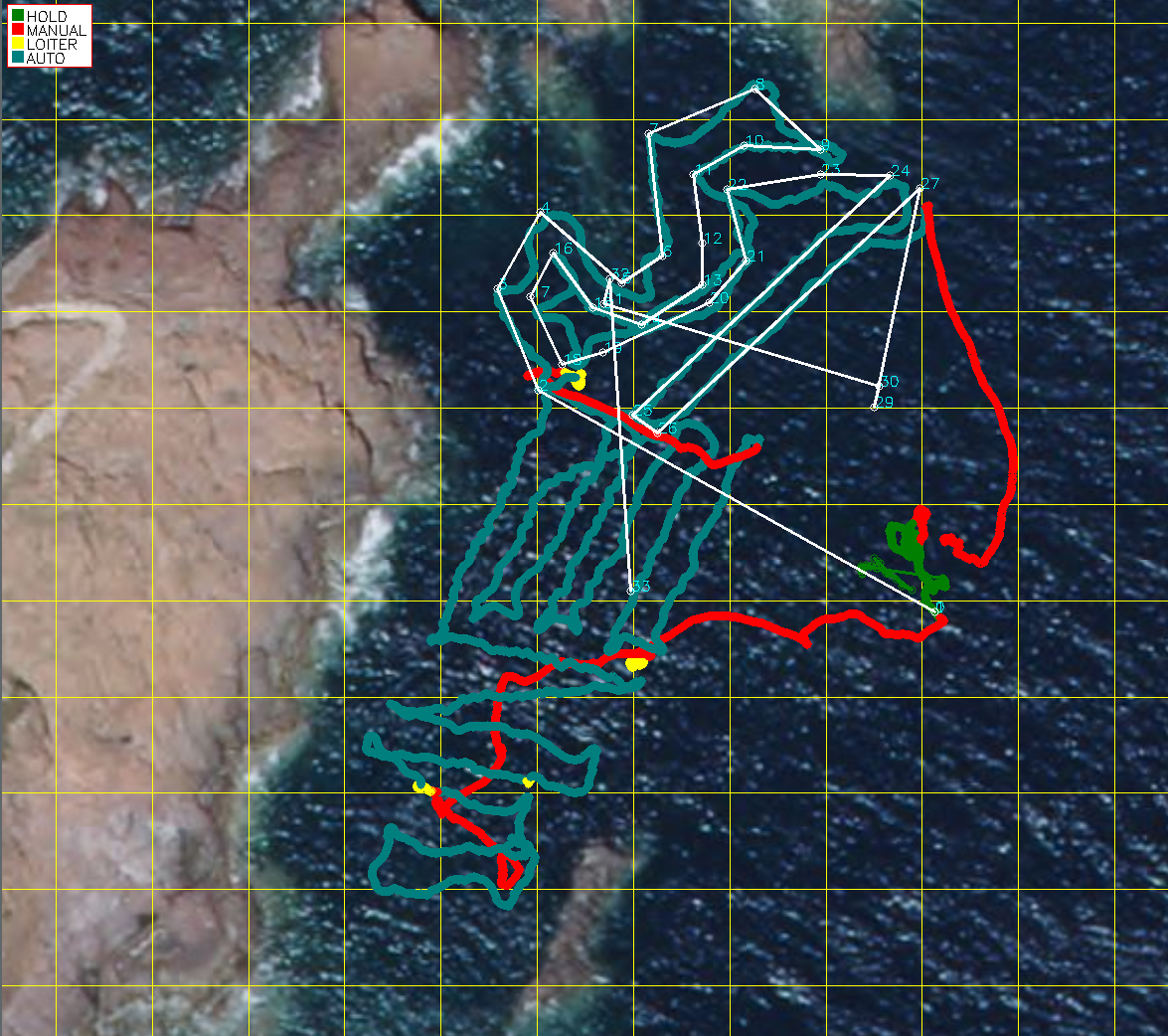
Operating modes :
- ■ Auto: Autonomous waypoint trajectory.
- ■ Hold: Safety state with motors off.
- ■ Manual: Operator-controlled.
- ■ Loiter: Maintain a fixed GPS position.
Capabilities:
- Speed matches the acquisition rate.
- Waypoint trajectory can be dynamically updated.
- The platform maintains its trajectory even in strong winds and large waves.
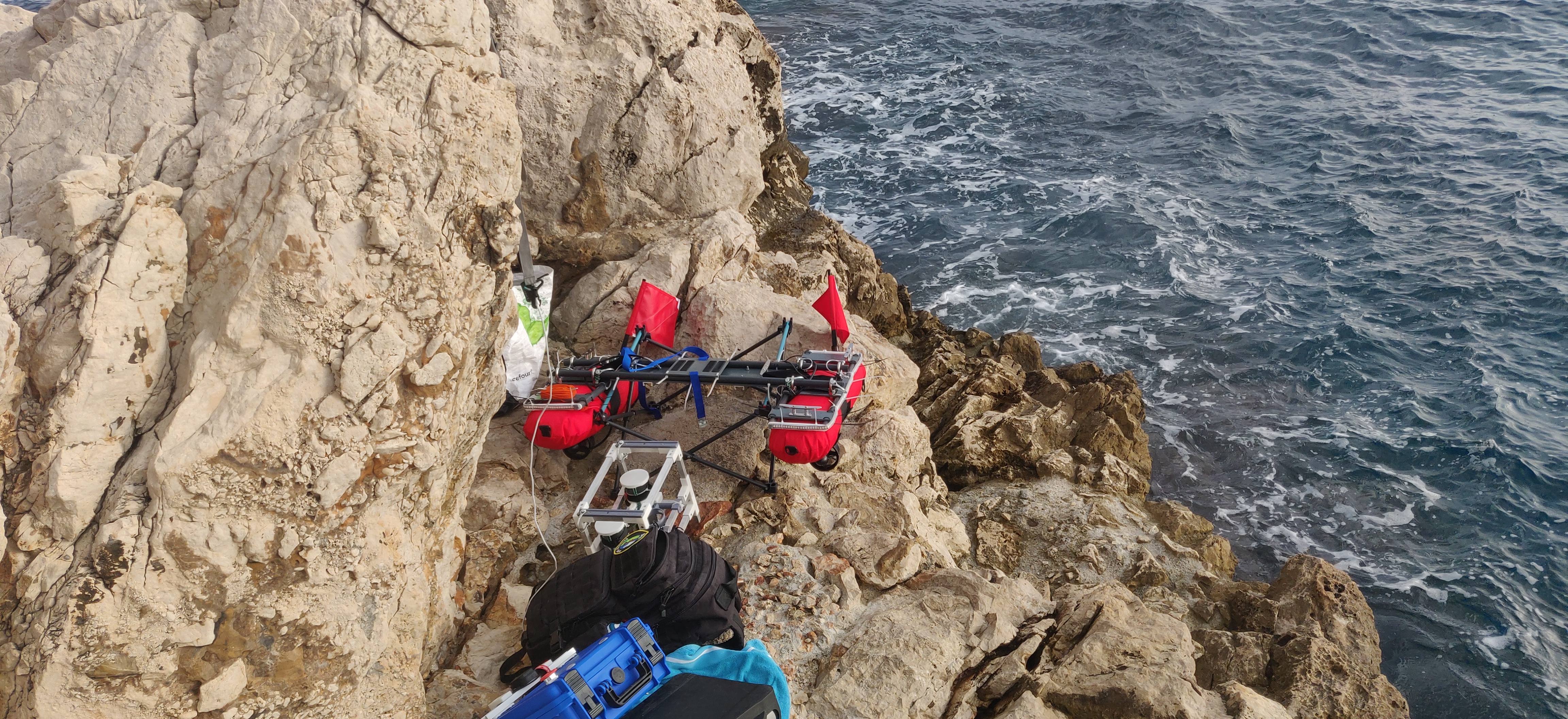
![]()
Acquisition mission


- 3 field missions.
- Nice and Saint-Raphael locations.
- Submeeting 2022:
- 13 images datasets acquired.
- 2 diving sites.
- Acquisition from surface and divers.
![]()
Acquired images processing
Processing:
- Initial pose estimation and calibration performed with Colmap.
- Micmac refinement utilizing GPS image locations and rigid constraints between cameras.
Result:
- Synchronization between cameras is insufficient for rigid constraints.
![]()
![]()
Synchronization variation
![]()
First Conclusion
- Multi-camera synchronized underwater system.
- Modular autonomous unmanned surface vehicle.
- Conducted field experiments and data acquisition with low-cost components.
![]()
Structure from Motion
Context

Different strategies for reconstruction :
- Incremental.
- Global.
- Hierarchical.
![]()
Preprocessing

- Use MicMac for features extractions and viewgraph creation.


![]()
![]()
Initial Pose Estimation Approach

Pipeline

Contribution:
- Score triplet of image in a viewgraph.
- Propose an initial pose estimation from triplet tree.
Requires:
- Intrinsic calibration data.
- A view graph representing relative orientations.
- Image triplets list along with the matched feature points.
![]()
Triplet Graph


In a practical scenario involving 100 views:
- There are approximately 10,000 triplets in total.
- A randomly selected triplet tree contains around 98 triplets.
- Scoring is performed on approximately 9,902 triplets.


![]()
Random Initial Orientation


The process for generating a random triplet orientation includes:
- Uniformly selecting a seed triplet and orienting its views.
- Randomly traversing adjacent triplets.
- Each traversed triplet orients an additional view.
- This continues until all views are oriented, forming the generated random tree.
![]()
Triplet Scoring


Triplets not included in the randomly generated tree are used for scoring. The scoring process utilizes the feature points visible in all three views of each triplet.
![]()
5 Points Virtual Feature Points

Since the method employs reprojection error at multiple stages, the scoring and bundle adjustment steps are optimized by using 5 virtual points instead of the original feature points.
Weighted HyperGraph


![]()
Best Initial Orientation


Using a Prim-like algorithm (Prim 1957) on the hypergraph, we obtain a subhypergraph solution that can be utilized as a tree to orient our views in the context of our problem.
![]()
Results - Initial Pose Orientation
Each view is oriented based on a triplet from the optimal tree.
Certain triplets may be selected that incorrectly orient the remaining branches.
Orientations are compared to a reference by transforming coordinates and comparing pose positions.
The reference is generated using all available information for each dataset.
![]()
Hierarchical pose optimization
Pipeline

Contribution:
- Split and Merge technique.
- Hierarchical scene decomposition based on triplets.
- Robust merging of image block using spanning triplets.
- Local bundle adjustment during merge.
![]()
Orientation Decomposition

Traversal of the tree follow a depth-first order.


Initial Orientation of Leaf Pose
Before starting the reconstruction, each leaf is assigned the pose from the Final Initial Orientation part.

![]()
Leafs Merge


During the traversal, each sibling is merged using the crossing triplet.
![]()
Reference Datasets
Drone

Temple
Underwater
![]()
Results
To evaluate the method’s quality, result orientations are compared to the reference orientation through coordinate transformation.
The initial pose orientation and its hierarchical optimization are analyzed.
For comparison, the classical Colmap automatic pipeline is also evaluated.
![]()
Results
Drone distance in Meters to reference orientation.
![]()
Results
Temple distance to reference orientation.
![]()
Results
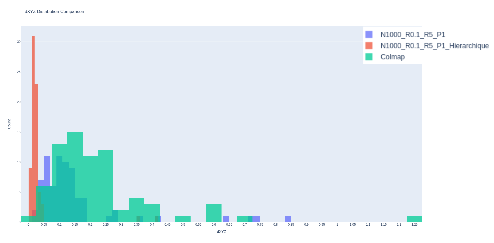
Underwater distance to reference orientation.
![]()
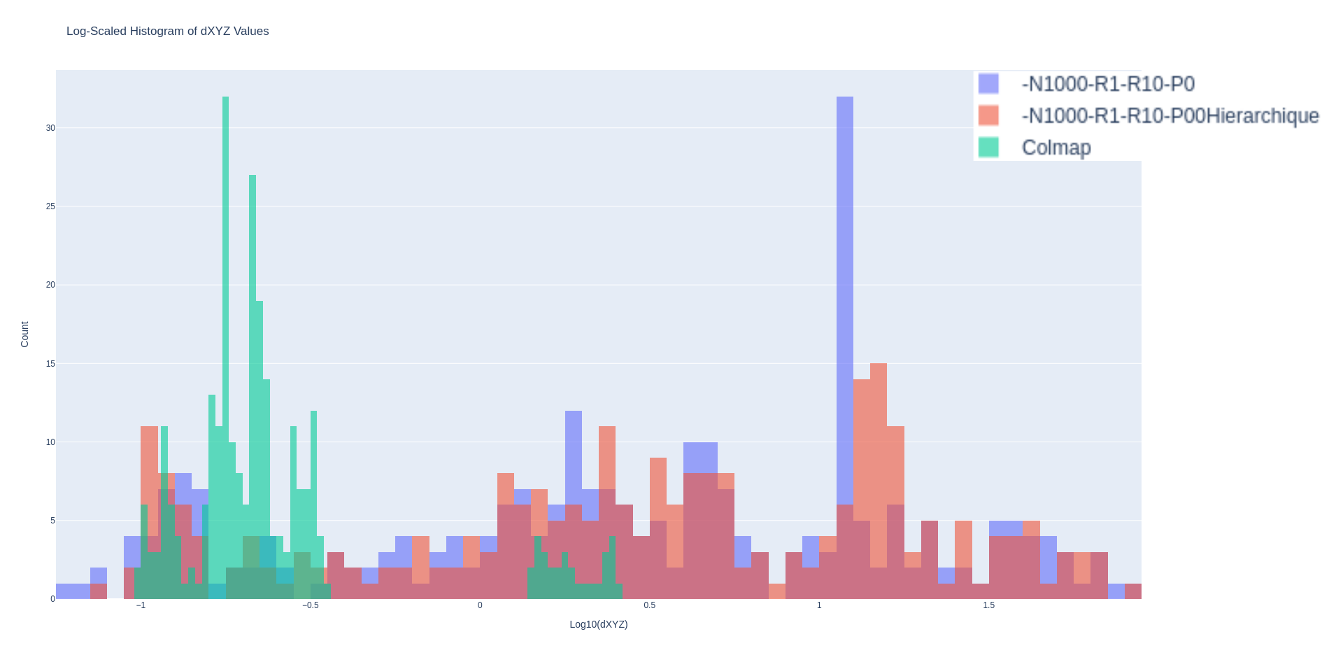
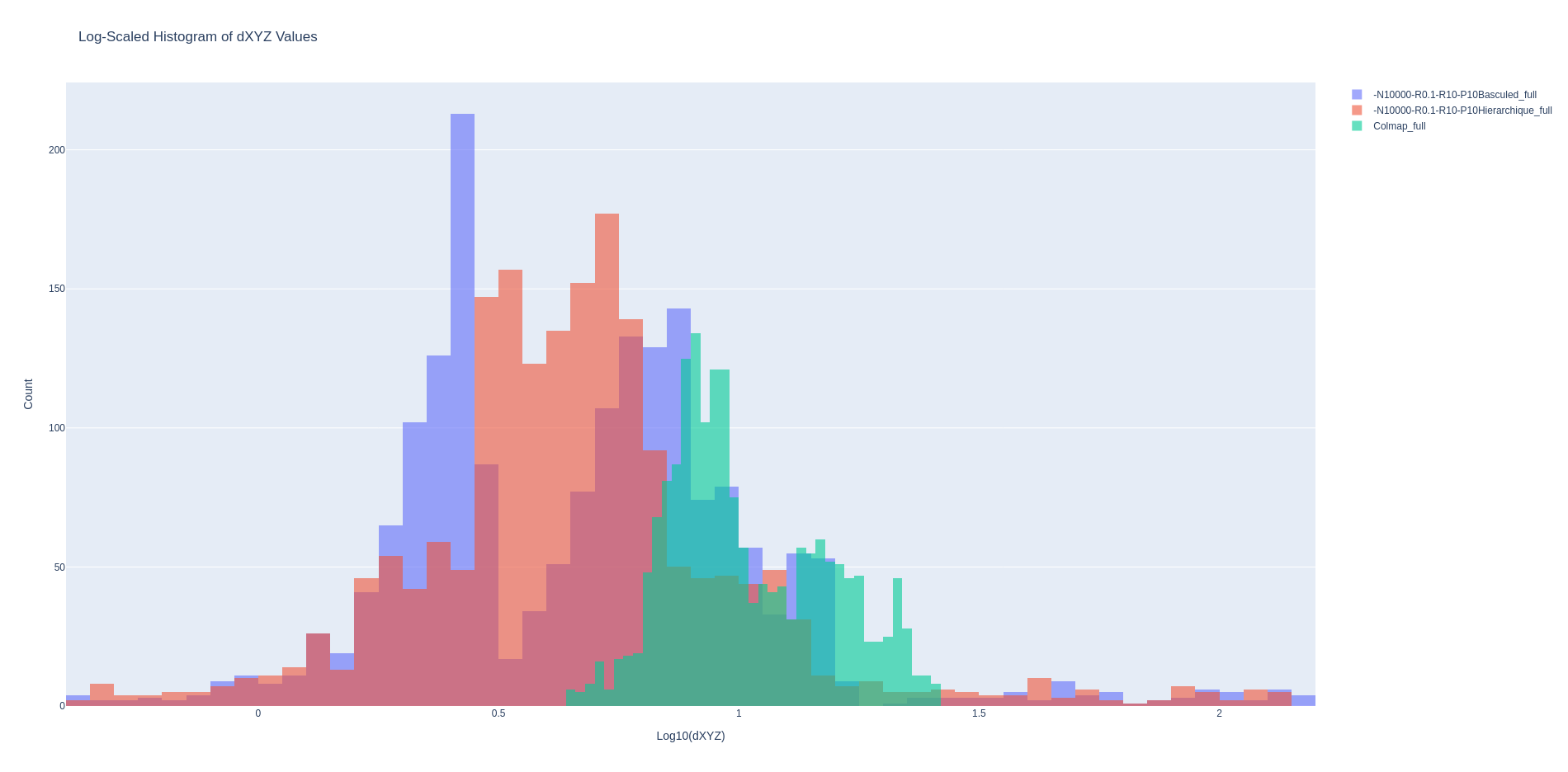
Results - Underwater
- Certain branches of the tree may experience incorrect initialization.
- For method comparison, the coordinate system is aligned with that of the reference.
- This coordinate system change introduces a bias in result estimation.
- Consistent output orientation relative to the reference, excluding poorly initialized blocks.
![]()
Results
Underwater Histogram filtering wrongly oriented image block.
![]()
Results - Point Cloud
![]()
Second Conclusion
- Initial Pose Estimation Approach:
- Utilize image triplets in random orientation for view graph weighting.
- Hierarchical Pose Optimization with Triplet Trees:
- Apply Divide and Conquer strategy to optimize orientation using all available information in the scene.
![]()
Conclusion
- From data collection to scene reconstruction.
- The first part focuses on data collection.
- Gather information to facilitate pose estimation.
- The second part focuses on general pose estimation.
- Initial pose estimation and subsequent optimization.
Perspectives
Acquisition
Short-term:
- Improve camera capabilities robustness.
Processing
Short-term:
- Study other scoring approach for the triplets.
Long-term:
- Fleet of acquisitions platform.
Long-term:
- Study graph-cut approach to resolve initialization.
![]()
![]()